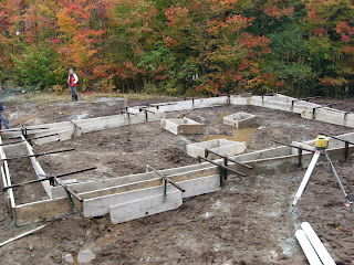
Here's a picture of my lovely wife and assistant cutting 2'' Styrofoam SM boards for the foundation. She's very crafty with a knife. We are installing 4'' on the outside and 2'' on the inside. Today we nailed it to the sill on the outside. We'll need to nail into the concrete on the inside. Hello power drill.
This gives us R-30 insulation value. Overkill? Not with a radiant slab. The temperature of the slab will be maintained at 75 C (22 C) whereas the temperature of the air will be closer to 65 F ( 18 C) (for very toasty toes). If you want to keep the heat in, you need to insulate the slab. Moreover, with a solar system you want to store solar heat from the day and summer through the night and winter. You need to insulate below the slab as well.
Friday, October 30, 2009
Installing Electricity
We had the temporary power supply for the workers installed on Tuesday. As soon as the house is enclosed, we're taking this puppy inside into the utility room once the house is enclosed. We still haven't decided whether to take the main power line (seen snaking into the panel at left) into the house through the frame wall or to drill a hole into the foundation wall (seen at right). Decisions, decisions. The piles of 1/2" clear, crushed stone in the background were delivered today
and will eventually fill the foundation and act as a bed for the hydronic slab.
The electrician actually had to come back on Wednesday to install our new address on the private pole shown here. Had to call town hall at Frelighsburg to find out what it was; they gave me all the permits, but not the adress! If you look carefully at the top of the pole you will see it.
The excavator and electrician cooperated very nicely to install the hydro pole. A few tense moment ensued when we found rock ledge a foot under the ground where the pole was supposed to go. Had to move it about 12 feet away from the drive (it was supposed to be inline with the oak tree shown at right). Fortunately, the electric line reached the pole.
Installing the drains
Martin (the plumber)of Plomberie Gilbert and his helper Ben arrived from Knowlton today on short notice (Alex told me this morning that he was coming to install the interior drains). Much to his relief, our foundation was not yet filled with crushed stone, making the work much easier.
The first order of business was to install the coil for the solar heat dump. The solar heat dump keeps the tank and solar collectors from overheating in the summertime when the need for heat is low and the supply of sun abundant. Martin pulled it out into a boingy slinky shape to help dissipate the heat even more. I'll be adding insulation above the coil to assure that the heat goes into the ground instead of to the slab, and to isolate .
Bill Northey and the technicians at Radiant Floor Heating Company customized the coil by adding two elbows and 42'' tubes to bring the cooling fluid from the ledge to the slab. He recommended burying in sand (instead of crushed stone) to maximize the thermal contact with the ground. The heat dump itself is pictured in the second image at lower right. We used it to measure out the position of the coil relative to the other plumbing.
Also shown here are the sewage drains under construction and, in the third image, completed. The main sewage drain runs out the hole in the foundation wall at back. You can actually see the top of the septic tank too. The floor drains runs out int he corner at left. The cruched stone supports the toilet drain. The whole foundation will eventually be filled with the stuff.
Great work by Martin and Ben.
Wednesday, October 28, 2009
Electric line and septic tank
Another busy, grey day on he house site. I got up early to cut down a few trees that were in the way of the power line.
Today, we installed the electrical line. This runs from a private poll installed by Normand (the excavator) and Camille the electrician. Bell contractors came along to install the public pole (in Frelighsburg, it's Bell and not Hydro that installs the poll). The private poll holds the meter and is where the line runs into the ground. It then goes across the driveway and up the hill along with the phone line and the line between the septic tank and tile bed.
Normand also trucked in generous amounts of sand to bury the septic tank, to make a bed for the French drains, bury the power line (need 2 feet of sand around power line), and just clean up the site. It covers up a lot of the mud.
The electrician also set up a temporary electric panel for the builders. Hopefully, it will be switched on by Hydro by the end of the month. I had orignally wanted the power cable to enter through the foundation, but the electrician figured it would be better to go through the wall above ground. A vistit from Alex the builder/carpenter changed that. He preferred the foundation option. I'm now considering renting a drill to bore through the foundation.
Sunday, October 25, 2009
The naked foundation
Here it is folks: the foundation, "tous nu"! We're about to install the weeping tile around the footings tomorrow, and will backfill some tomorrow, so I figured I better get a few pictures. Normand the excavator was in the neighborhood with the backhoe and bulldozer, so he kept it at our place over the weekend. He'll be installing the septic tank The electrician will be installing the buried power line and private pole on Tuesday. Hopefully Bell will show up to put in the hydro pole (they were supposed to do it last Thursday).
Here's a detail of the anchor system. These anchors will hold the posts in place with bolts. Should be good for up to F2 tornadoes.Looks like the frost took a toll on the corner of the foundation. Other than this, the foundation is straight and smooth.
I've posted a panorama of the house site. Not only is the house progressing, the seasons are too. Hope the snow holds out.
Sunday, October 11, 2009
Friday, October 9, 2009
Setting up foundation forms
One of the fun things about hiring contractors and being on site is that you get to watch people do the stuff they really know how to do. The tools of the trade arrived on flatbed trucks. These racks of wooden concrete forms were hoisted onto the site using a crane. Because this foundation has pilasters, it required a lot of pieces not used on most building sites.
When I saw them, I realized why a lot of foundation contractors prefer these to styrofoam forms. These are 1 inch thick plywood with cast iron links. That's a little more sturdy than styrofoam and less likely to collapse when you climb over them or during a pour.
I caught Roger Laroche looking at the camera as he assembled them. This was the only time. He's in and out pretty quickly with his team, and watching what he's doing during that time. He came yesterday with one worker to set up the forms. Either the plans I gave him had a miscalculation, or I had given him an older version of the plans. With all the wonky post positions and the calculations for styrofoam forms, something just didn't add up. Instead of trying to figure it out, we went back to the timber framers plans and wall system to figure out the positioning of the pilasters and that the exterior of the foundation wall needed to be 5 inches out from the posts.
Lessons 1 - Burn all old versions of your plans
Lesson 2 - Make sure your contractors know what they're building.
This morning I checked the measurements and it all checked out, but the interior post footings were off; fixed it. Roger and I double checked the post positions together before the pour: measuring tape was flying everywhere. Roger used string wrapped to nails on top of the forms to line up the post positions to make sure they'd be resting on pilasters. Roger then used them to position the post anchors into the concrete. Double checked these after. One was half an inch off.
No pictures of finished pour today. Camera was out of batteries, and I was too busy measuring to take pictures.
The final footings
Here's a nice view of the finished footings. Surprisingly (to me), they took one relatively damp afternoon to dry. The water just rises to the top and either evaporates or runs off. The three footings inside the house are for the chimney (right) and interior posts (two footings at left). These were poured about a foot too far to the left. I caught it though with my trusty measuring tape. The foundation contractor just extended them one foot to the right. Good save, Roger.
Concrete, if used correctly, is a fine thing. Sure, it has a nasty carbon footprint, but note how the footing keeps the water from that little spring pooling in the crevice at bottom right. This is good, because it is not pooling inside the house. Water pooling under the house is not environmental; it leaves mold. We filled this pool with extra concrete left over after the foundation pour. The spring now drains behind the house (to the left of the photo).
Thursday, October 8, 2009
Final wall system
Well, I screwed up a calculation on the foundation pillasters and confused the foundation contractor. Had to recalculate on the spot. Good thing I had everthing on this blog to print out.
Given that the foundation forms are now up, this will have to be the final version of the wall system. Features include:
- 2' footings
- 8'' walls
- wall height 2'-3'
- 8'' pillasters to support posts
- foundation walls protrude 5'' from post exterior
- 4'' SM insulation outside foundation
- 2'' SM insulation inside foundation
Rebar
Two lines of horizontal rebar was placed in the poured footings after the pour to reinforce the concrete. Roger Laroche and his helper very quickly cut and bent the vertical rebar using a cutting and bending tool. Roger can be seen here laying the vertical rebar into the footings as I look on anxiously, wondering how much this is all going to cost (it should actually be close to the estimate; Roger said that the site was actually easy to work; I believe him; it took him a morning of work to do all this).
Three steps were built into the footing. The largest is seen here is along the back wall and is about 10 inches in height. Roger built these with conventional forms in mind. Styrofoam forms for foundation walls would have required more precise (and hence labor intensive) step measurements.
The rebar (which will anchor the walls to the footing) is offset slightly to the outside perimeter of the footings to allow for interior pilasters in the foundation wall. Two vertical rebars are placed where the post-supporting pilasters will be poured into the concrete wall.
The the far right of the image also shoes the trench in the rock that runs behind the house . It should divert water from the spring away from the house.
Drainage on north side of house
Because the surface bedrock we are on is an impermeable chlorite schist, any downpour or spring thaw will run off on top the rock. This means that we should take advantages of natural cleavages and ruts in the bedrock to divert any water away form the foundation footings.
The north side of the house is naturally drained by a crevice that Normand managed to excavate with the bulldozer. I'm glad he did because it allowed us to position the house adjacent to the crevice as opposed to over it! It actually does run under the northeast corner of the house seen in the back of the image. Fortunately, it is not as deep as pictured in the foreground.
To make sure the part of the crevice under the house drains, we placed a drainage tube under the footing (pictured here at bottom). The water line from the well will run through the top tube. The backfill will will be about 3-4 feet here and be covered by a board of Styrofoam SM. That should keep the water from freezing in the wintertime. Hopefully, we'll manage to keep water from entering under the house at all by draining the water into that rut that runs behing the house.
Drainage for spring
A small spring in the driveway uphill from the house drains towards the house. It pools in the middle of the house (seen here). At bottom left is the little ditch in the rock that carries the water to the house. The footing forms block the flow in the picture. The square footings int eh middle of the house are for the chimney and the two interior posts.
Here I am filling the ditch with excess concrete dumped from the hold of the pump truck. The idea is to divert the flow to the left behind the house where another ditch will carry it away from the foundation. We will fill this ditch with weeping tile and crushed stone to make sure it drains this way.
It's not as tough as it looks. The concrete mixed with the water and proved to be quite easy to shovel over. Mind you, I wouldn't want to bend over like this all day. This should divert runoff to behind the house for now. I couldn't fill all the way to the footing because the contractor will need to remove his forms. We will fill in that hole when we pour the foundation walls (will be about 3 to 4 feet high).
Pouring the footings
The original estimates for the foundation all included an extra item for a concrete pump that would make work ont he site easier. We thought it would have to be a hell of a pump to justify the cost. Little did I know it was a whole truck. Here the cement truck pours the concrete into the pump truck, which delivers the concrete with this huge crane. The concrete workers pour the concrete.
The concrete is 25 MPa concrete (that's megaPascals) for both the footings and foundation walls. According to my calculations, that means it can withstand 100 000 kg loaded onto the 8''x8'' hemlock posts that the foundation will hold. Obviously, the concrete is not the weakest link in the house. It was dry and ready to walk on in about 6 hours. We had ideal conditions for drying: no rain, a little sun in the afternoon, temperatures around 15 C and a light breeze.
Here's a closeup of the contractors. The concrete is from Beton Cowansville. The concrete contractor stands at left as Laroche pours and his journeyman helper evens the pour.
We thought that the footprint of the house was awfully small. I double checked a few measurements and they all checked out. The walls will actually stand slightly offset to the outside, so that there is actually a foot more interior room than there appears to be with just the footings.
Wednesday, October 7, 2009
Forms for footings
We went with 2 foot footings directly on the rock. I'm glad we did. A 2-foot barrier bonded to the rock should divert away any runoff moving along the top ot the rock.
The plans for the foundation are outlined here.
The foundation contractor (Laroche et fils) showed up with a flat bed and crane that deposited and a nice portable tool shed on the site (see previous post). The excavation had actually left the site more even than anticipated, despite some undulating crevices and depression that caused the water to pool. All in all, the footing ended up having only three steps, and the final height varies by no more than a foot.
This image shows where the footing is at its thickest at the corner of the "shed" extension. The footing actually dips into a crevice in the rock that will act as a natural drain for the north side of the house.
Diagram of well
This is all you can see of the well now.
Here's the diagram of the well with all the relevant statistics. The back fill has yet to be added. We hit water at 60 ft but needed to continue until about 180 ft to get a decent fill rate of 100 gallons/hr. The water levels off at about 30 ft below the surface. The reservoir of water is about 135 U.S. gallons or 620 litres.
The bentonite collar is necessary in the code to prevent infiltration from surface water because we are directly on the rock. Bentonite is a type of concrete that expands enormously when it comes into contact with water. It added a nifty $1700 to the cost of the well :-/ .
Tuesday, October 6, 2009
Loading up and going home
This is the drill all ready and loaded, waiting to be walked down the hill and taken home. I think it looks more like a rocket launcher here. The drill operator (seen in both pictures) consulted regularly on well depth.
The cool part is that the control panel is portable and can be used to drive the machine just about anywhere. Lisa called me a geek for taking this picture of the operator taking the drill machine down the hill . I just think it makes me a guy: what man can resist enjoying the dual pleasures of a remote control and heavy machinery?
Setting up the drill
The well drilling platform is this neat little crawler that can actually get into much tighter spots than our well site. It needs to be hooked up to a water and power source, which in this case was a supporting truck seen in the previous post. The thing at the left that looks like a lunar landing craft expels all the rock that the drill flushes out with water that is pumped through the tubes you see lying around the bottom. The next device over is the control panel for the entire operation. It's actually used to drive the machine as well as operate the drill.
Busy worksite
We were expecting the well people from Puisatiers Exprets from Granby this morning. I hear action at the site, grab my well permit, and rush up to the site only to find the people from Laroche et fils getting ready to build the footings for my foundation. So I rush down to finish my foundation plans.
It was a busy worksite, but manageable. The contractors seemed to know how to stay out of each others way. Good thing, because there was a lot of coming and going. I managed to get some work in myself, although I was not nearly as busy as I appear to be here. Here I am moving the leftover concrete from the pump truck. I'm using it to block the runoff from a small spring in the driveway. This should help divert the water from a natural crevice under the house to a natural crevice running BEHIND the house.
Roger Laroche inspects his footing pour at far right, and the well guys drill for water in the background.
Thursday, October 1, 2009
Fixing the driveway
We needed to scrape the grass and add some crushed stone to shore up the driveway up the hill.
We added some extra stone to even out the grade up the steepest part of the hill. The bed of the old gravel road had been slightly washed out in this area. With this bed of crushed stone, we're all set to have any heavy machinery come up to the house site, and less likely to get stuck coming up the hill. Here Normand the excavator spreads out the first load of crushed rock. Lisa peeks above the shovel.
Subsequent photos show the second load arriving and the finished job.
Subscribe to:
Posts (Atom)