Thursday, September 24, 2009

Windows and doors: Description

Pantry
  • 1 Casement 2'6''x2'6''


Second floor

  • 2 Double hung: 4'10'' x 2'6''

Kitchen
  • 1 Double Casement 3'4h x 4w'
Bedroom
  • 2 Double hung: 4'10'' x 2'6''
Bathroom:
  • 1 Double Casement: 2'6''hX5''w
  • 1 Double hung: 4'10'' x 2'6''

Cathedral wall:
  • 2 Fixed (upper): 4'10'' x 2'6''
  • 2 Double hung: 4'10'' x 2'6''
  • 1 Casement: 3'4'' x 2'6''


Living Area (south and east side):
  • 6 Double hung 4'10'' x 2'6'' :
All this will take away from the "old farmhouse" look we're trying to get from the outside, though.

Tuesday, September 22, 2009

Current foundation system and footprint

This foundation option shows
  • 2' wide footing on the bedrock.
  • 8'' (7 7/8'') foundation wall (2'-4' high) supporting insulated wall truss system
  • 8'' pilasters to support posts of timber frame.
  • 21/2'' insulated concrete forms (Aarx)
  • 2'' Styrofoam SM board on outside of foundation; flush with sheathing from wall system
  • High point is on southwest corner of house.
It will be built in the following sequence:
  • Footings layed on bare rock; footing for chimney and interior posts anchored to stone
  • ICF's put in place, sill anchors and sub-floor utility cut through ICF's, and walls poured
  • Weeping tile placed to drain interior; layer of clear stone placed to cover weeping tile; moisture barrier put in place; all interior covered with clear stone
  • frame and roof built on foundation walls
  • hydronic heating tubing and equipment installed and 4'' hydronic slab poured
Dimensions of forms are for Aarx ICFs. Cross section shows an 8'' wall with an extra 2'' of styrofoam insulation (R-35; total extra cost $800 for extra styrofoam assuming 3' high wall all around). ICF's represent equivalent insulation value of $2000 worth of Styrofoam SM insulation.

I've consulted various foundation builders on the feasability of pouring a concrete wall directly onto the bedrock using insulated concreted forms (ICFs). Even the contractors (along with representatives form the ICF manufacturers) willing to do it said that it is less labor intensive and hence cheaper to build a stepped footing directly on the rock, place the ICF's flat on the footing, and pour on the walls onto the footings. It appears any saving in concrete is mitigated by the awkwardness and increased labor costs of scribing the ICF's to the rock.

A 2ft-wide footing also has the advantage of a) being more resistant to washout than a 10'' foundation wall b) not requiring drilled rebar (the rock is undulating and uneven, so that footings will be be held firmly in place), and c) being decoupled from the actual foundation for a certain amount of seismic damping in the event of earthquake.

That makes this the preferred option.
References:

Tuesday, September 8, 2009

Revised wall system I


This is a revised wall system using insulated concrete forms (ICF's) from Arxx.

The cross section does NOT include the posts and pilasters for the timber frame.

The wall system above is flush with the foundation/form system below.

References:

Monday, July 27, 2009

Hydronic installation

The image at right shows the hydronic heating components in the utility area near the house entrance. Not that the hot water tank also provides domestic hot water. The circuits are color coded for clarity. They are not exactly to scale, but give an idea of the space involved.

The following circuits are mounted on the wet wall. Cylindrical tanks represents expansion tanks. Long boxes represent circulation pumps.
  • Hydronic floor circuit: this circulates hot water through the pex tubing in the hydronic slab. Water enters and leaves the slab through a slab manifold. Hot water leaves the circulation tank at the top. A valve allows hot water to be drained from the circuit for domestic use (not shown). Cold water from the well reenters the system through a valve further on in the circuit, so water continuously gets pumped into the floor. It renters through the bottom of the tank to be reheated.
  • Solar loop: Heated antifreeze comes from the solar panels on the roof. It enters the heating exchanger coils in the bottom of the tank. It exits about halfway up the tank and flows back to the heating panels. A heat dump short-circuits this flow when the fluid entering the tank exceeds 160 F. This protexts the solar panels form overheating. The fluid is run through a copper coil buried under the house designed for this purpose.
  • Electric boiler: An electric boiler acts as a backup heating device for when there is not enough sun to supply the system. The heating contractor recommends a 13.5 kW boiler. The circuit feeds into a coil at the top of the water tank.

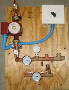
Single zone open system

The following images illustrate the open system "Radiant Ready" system from the Radiant Floor Company that transports hot water from the tank to the floor and domestic hot water circuit.
  • Hot water leaves the heat source (hot water tank in this case). The domestic hot water pipe may divert the supply, but this is replaced by water from the well.
  • The water then passes through the pump. Notice that the water must move upward through the pump in this design.
  • The water then passes through the floor and returns to the tank through the pipe at the bottom of the fixture.

Saturday, July 25, 2009

Slab manifold

The slab manifold is the junction between the copper tubing of the hydronic system and the pex tubing running through the slab. This comes in a wooden box. The concrete slab is poured around the wooden box, and the wood removed once the concrete is dry. The hot water tubing is then attached to the manifold.

Images here show the manifold before and after the slab is poured.

Thursday, June 4, 2009